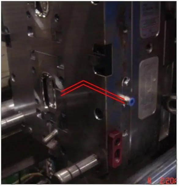
In the process of injection mold debugging, defects such as surface bubbles, lack of luster, burn marks, difficulty to fill, etc. Sometimes after adjusting the injection molding process parameters many times, we still can’t solve the problem, then we can consider whether the problem is caused by the mold venting system.
Where does the gas in the mold come from?
Gas in the mold is mainly generated by the following:
- Air existing in the pouring system and in the mold cavity;
- Some raw materials contain water that has not been completely dried, and they vaporize into water vapor at high temperatures;
- Gases generated by the decomposition of certain unstable plastics due to high temperature;
- Plastic raw materials in some additives volatilization or mutual chemical reaction born gas.
What harm can be caused by gas in the mold?
If the gas in the cavity is not removed, it will bring a series of hazards to the quality of plastic parts, production efficiency, mold parts lifespan, and other aspects:
- During the injection process, if the gas is not discharged in time, it will cause difficulties in filling the melt, resulting in insufficient injection volume to fill the cavity;
- The gas trapped in the cavity forms high pressure, which may penetrate into the plastic, causing pores, cavities, loose tissue, silver lines, and other quality defects;
- Gas in the process of high compression makes the temperature inside the cavity rise sharply, so that the melt decomposes, burning so that the plastic parts appear local carbonization and scorching phenomenon. It mainly appears at the merging of two melt streams and at the flange of the gate; the poor exclusion of gas makes the melting speed into each cavity different, so it is easy to form activity marks and fusion marks and make the mechanical properties of the plastic parts lower;
- The obstruction of gas in the cavity will reduce the mold filling speed, affect the molding cycle and reduce the production efficiency.
injection molding venting design
For injection molds with small exhaust volumes, we can use the gap between the mold parting line and the mold component to exhaust naturally.
For injection mold with large exhaust volume, or mold with precision, high speed, and high-quality requirements, we need to design the injection molding venting system;
Mold in the design stage, CAD/CAM/CAE, and other software with mold flow analysis provide good help for the design of the venting system, but for the complex structure of plastic parts, it is difficult to estimate the specific location of air resistance occurring in the mold before molding, so we will also add and modify the venting system according to the condition of the test mold and the characteristics of the plastic parts during the mold injection debugging.
Generally, we will design the following mold vents solutions:
Air Vent
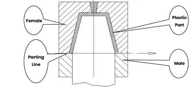
We usually choose to open a venting groove at the parting line
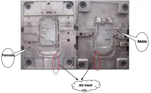
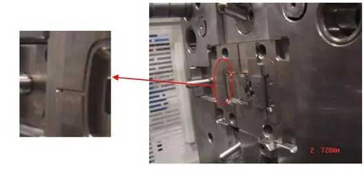
The venting groove is opened on the parting line, generally at the most remote point opposite the gate (i.e. the last part of the cavity to be filled). It is best to open it on the side of the Famale mold so that the resulting burr can be discharged with the molded part. The depth of the venting slot should not be greater than the overflow gap of the molded part. The width of the exhaust slot is generally 1.5-6mm. After the mold is shut down, the exhaust slot will be corroded by air condensation, thus blocking the exhaust channel. Therefore, you should check or clean the exhaust slot before using again to make sure the exhaust system is smooth.
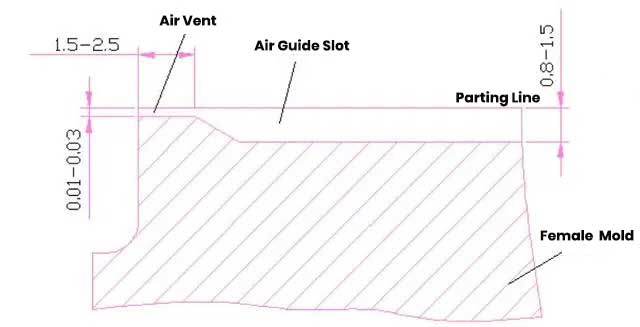
The depth of the venting slot gap is determined according to the characteristics of the plastic, generally ranging from 0.005 to 0.02mm. In order to make the venting more smooth, the venting belt is often opened in the part below 0.5-1mm from the molding line, and the depth of the venting belt is about 0.2-0.5mm.
Natural Venting With Mold Parting Line Or Mating Gap
Venting using parting line:
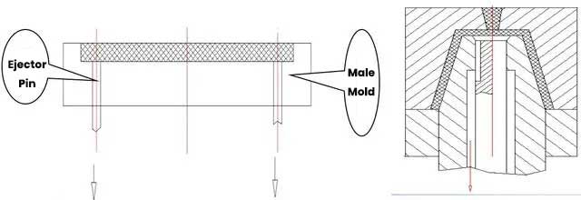
Use the clearance between the ejector pin and the male mold plate to vent the air:
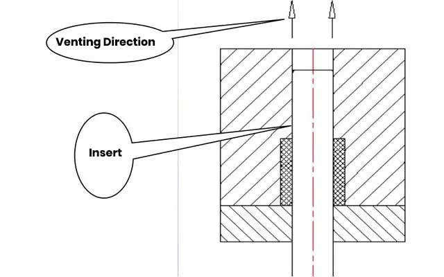
Use the gap between the insert and the cavity to vent the air.
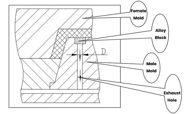
Inserting metal block to vent
When the last filling part of the cavity is not on the parting line, and there is no puncher or movable core for venting in its vicinity, the corresponding part of the cavity can be inlaid with a sintered metal block (porous alloy block) for venting. But it should be noted that the diameter D of the ventilation hole under the metal block is not too large, so as to avoid deformation of the metal block under stress.
Venting Ejector Pins

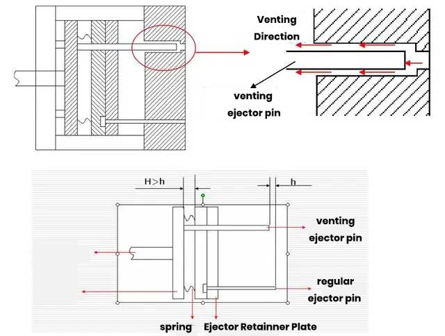
When the melt first enters the mold cavity, the piston ejector pin is lower than the mold line by a distance h (as shown in the figure), at this time, the gap between the piston ejector pin and the mold can be used for venting.
According to the multiple short shots to confirm the melt in the piston ejector pin to avoid empty position for sealing time and route.
Set the waiting time for in-mold ejections and the ejecting speed of the piston ejector pin to ensure that the ejector pin seals the melt when it is about to reach the empty position of the piston ejector pin.
Note: The ejecting distance of the piston ejector pin is until the ejector pin is parallel to the mold surface. Remember not to exceed the surface of the mold, so as not to damage the die.
Vacuum Venting System
When the venting groove can not meet the exhaust need, vacuum suction device can be used to enhance the exhaust of the mold.
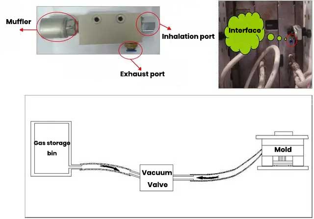
When the mold is closed and the injection starts, the suction valve of the vacuum valve will be opened and the gas inside the mold will be pulled out to remove the trapped gas.
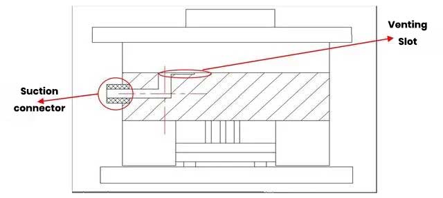
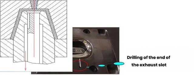
Two perpendicular holes are drilled at the end of the venting slot to ensure that the venting slot is connected to the outside, and then a suction fitting is installed. The suction action of the vacuum valve can then be realized. It is suitable for all kinds of product molds that are prone to air trapping. And low cost.
