What is the function of gates in injection molds?
The gate can be regarded as the last “door” for the molten plastic to enter the cavity through the feeding system and is the feed channel connecting the branch runner and the cavity. It has two functions:
- It controls the flow of plastic melt into the cavity;
- It blocks the cavity when the injection pressure is withdrawn so that the plastic that has not yet cooled and solidified will not flow backward.
How to determine gate size injection molding?
It depends on which gate type is used. Different types of gates are different. This article presents the thirteen most commonly used gates, each given a suggested size, and how to design and troubleshoot; please read the details by your choice.
There are many types of injection molding gate, and they can be divided into manually trimmed gates and automatically trimmed gates according to the method of gate trim.
Manually trimmed gates
Manually trimmed gates require a secondary process by the operator to remove the gate vestige. Why don’t using the automatic way instead?
1. The gate is too large and must be moved outside the mold before it can be cut out.
2. Some plastics are sensitive to shear stress (e.g., PVC). should avoid automatically trimmed gates,
3. automatically trimmed gates should be avoided when the melt from different directions flows through a large cross-sectional area simultaneously and when fiber orientation is required.
Manually trimmed gates are available in the following forms: direct gates, tab gates, edge gates, overlapping gates, fan gates, disk gates, ring gates, spoke gates, and film gates.
Direct Gate
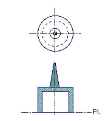
A direct gate, also known as a sprue gate, is usually used in single cavity molds, where the plastic is filled directly into the cavity from the vertical sprue with minimal pressure drop. This type of gate tends to leave a gate mark on the part’s surface after it has been cut out.
The solidification of the direct gate is controlled by the thickness of the part, not the gate thickness. Usually, there is not much shrinkage in the area close to the direct gate, but there is a lot of shrinkage at the direct gate, resulting in a lot of tensile stress.
The diameter of the inlet end of the direct gate is related to the diameter of the ejector nozzle, which must be at least 1mm larger than the diameter of the ejector nozzle. The standard vertical sprue bushing has a 2.4° taper opening to the part end, so the length of the direct gate controls the diameter of the root of the gate at the part end, which must be at least 1.5 mm larger than the part thickness, or approximately twice the part gate thickness.
The taper angle of the direct gate should be at least 1°. Too small an angle may prevent the vertical sprue from separating from the vertical sprue bushing during ejection; too large an angle wastes plastic and increases the cooling time. A non-standard taper angle of the vertical sprue is more expensive to process but has little benefit.
Pros
- Good flowability.
- Simple structure.
- Wide range of applicable resins
- Good fill ability of the material.
- Low surface shrinkage and sagging.
- No need to process the runner
- Less pressure loss
- Can form large or deeper molded products.
Cons
- Only one molded part can be formed at a time, and it is impossible to take several multi-point gates unless a multi-nozzle molding machine is.
- The appearance and subsequent processing are affected by the residue of the gate.
- Flat and shallow molded parts tend to warp and twist.
- We need to consider the gate cycle.
- High residual stress near the gate may cause breakage or deformation.
Tab Gates
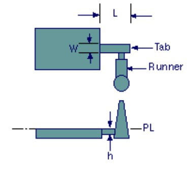
The tab gate is usually used for flat or thin parts to reduce shear stresses in the mold cavity. It is suitable for injection molding plastics with poor thermal stability and high viscosity, such as PVC and polycarbonate. The high shear stresses around the gate occur only in the auxiliary tabs and are removed after molding. Tab gates are often used to mold PC, acrylic, SAN, and ABS resins. The minimum width of the tab is 6.4 mm, and the minimum thickness is 75% of the cavity thickness. The tab gate is set at right angles to the branch runners, and the tab gate should be placed at the place where the wall thickness of the product is thicker.
Pros
- Low residual stress after molding.
- It can reduce the overfilling caused by injection pressure and the deformation caused by cooling.
Cons
- Higher injection pressure is required.
- It is necessary to remove the residual material from the sprue after molding.
Edge Gate
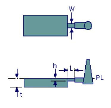
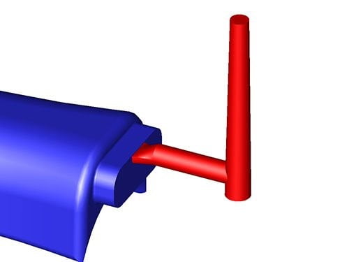
The edge gate, or the standard gate or side gate, is usually located at the mold’s parting line and is filled from the side, above or below the part. Typical edge gate size is 6% to 75% of the thickness of the part, or 0.4 to 6.4 mm, with a width of 1.6 to 12.7 mm, and the length of the gate face should not exceed 1.0 mm, with an optimum value of 0.5 mm.
Pros
- Low residual stress.
- Easy separation of the molded parts from the gate.
- Prevents material backflow.
- Abrasion heat generated in the gate can raise the material temperature and facilitate filling.
Cons
- High flow resistance.
- More loss of pressure.
- Insufficient flowability causes insufficient filling or solidification halfway.
- Due to the narrow gate, it is easy to cause bubbles or flow marks for flat or large surface area molded parts.
Overlap gate
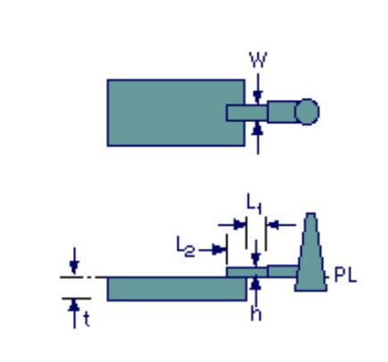
An overlap gate is similar to an edge gate, but the overlapping gate overlaps the side wall or surface of the part. Overlap gates are usually used to prevent the jet effect. Typical overlap gate sizes are 0.4 to 6.4 mm thick and 1.6 to 12.7 mm wide.
Fan Gate
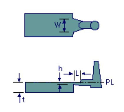
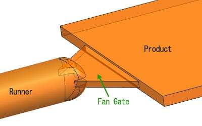
The fan gate is a wide edge gate with a gradual change in thickness and a large filling area that allows the melt to fill large parts quickly. Warpage and dimensional stability are very important for large parts, so the fan gate allows the melt wave front to fill the cavity evenly for large parts.
The width and thickness of the fan gate are tapered, and a constant melt front area is maintained to ensure a constant melt velocity, allowing the melt to fill at the same pressure across the wide side of the gate. As with other manually trimmed gates, the maximum thickness of the fan gate should not exceed 75% of the thickness of the part. Typical fan gate thicknesses range from 0.25 to 1.6 mm, and widths from 6.4 mm to 25% of the cavity side length. It should be noted that the cross-sectional area of the gate should not be larger than the cross-sectional area of the branch runners.
Pros
- Good flowability.
- Uniform filling to prevent deformation of molded products.
- Low gate alignment.
- Good appearance of molded products with almost no defects.
Cons
- Time-consuming to process the gate.
- It is difficult to cut off the gate part.
Disk Gates
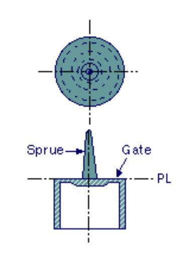
A disk gate, also known as a diaphragm gate, is commonly used for cylindrical or round parts with an opening on the inside, where a high degree of coaxiality is required or where no seam lines are allowed. The disc gate is a burr-shaped gate on the inner edge of the part, and the melt is filled into the mold cavity through the coaxial vertical gate, making it easy to obtain a part with uniform melt flow. The thickness of the disk gate is usually 0.25~1.27 mm.
Ring gate
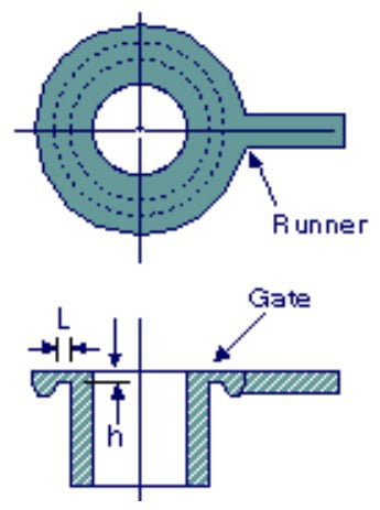
The ring gate is also used for cylindrical or round parts, where the resin is first wrapped around the center of the mold and then filled down the round tube. Ring gates are not suitable for all parts. The thickness of the ring gate is usually 0.25 to 1.6 mm.
Spoke gate
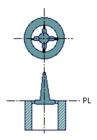
Spoke gate, also known as the four-point gate or cross gate, is used for tubular parts and has the advantage of easy gate trim and plastic efficiency. However, it may cause seam lines and cannot obtain perfect true roundness. Spoke gates are usually 0.8~4.8 mm thick and 1.6~6.4 mm wide.
Film Gate
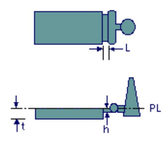
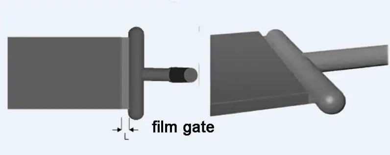
A film gate, also known as a flash gate, is similar to a ring gate but is used for parts with flat edges or forming tubular products. It has a flat gate, and the width of the gate can span the entire edge of the cavity or part of the cavity. Film gates are used for acrylic parts and are often used for large, flat parts to maintain a minimum amount of warpage. Film gates are small, approximately 0.25 to 0.63 mm thick and 0.63 mm wide. When the inner diameter of the product requires high precision, the film gate can be set at the end of the product, and the overlapping length of the gate should be not less than the thickness.
Pros
- Good flowability.
- Uniform filling to prevent deformation of molded products.
- Good precision for round-shaped products.
Cons
- Time-consuming to process the gate.
- It is difficult to cut off the gate part.
Automatically trimmed gates
Automatically trimmed gates work with the mold motion as gate cutters to shear off the gate when ejecting the molded part. They are used to:
1. avoiding the secondary processing of the gate removal.
2. Maintain a uniform cycle time
3. Minimize gate marks.
Automatically trimmed gates include the following types: pin gates, submerged gates, hot runner gates, and valve gates.
Pin Gate
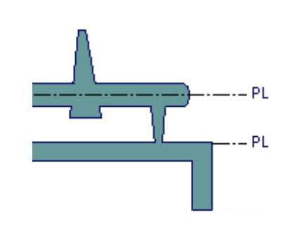
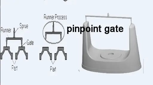
The pin gate, pin point gate, is usually used in three-plate molds where the runner system is located in one part of the mold line of the template, and the mold cavity is connected to the main part line. The pin gate has an inverted cone angle and penetrates the intermediate mold plate in the direction parallel to the mold plate movement. When the main parting line of the mold cavity is opened, the small diameter end of the pin gate is torn away from the part, and the runner scrap and gate remnant can be ejected by opening the runner parting line.
This system can open the runner parting line first and then use an auxiliary tool to tear off the runner scrap. Pin gates are often used in single parts with multiple feed points to ensure symmetrical filling or to shorten the runner length to ensure pressure-holding operation throughout the part. Typical pin gates are 0.25 to 1.6 mm in diameter.
If a pin gate forms thin-walled products, the product will be easily deformed or even cracked near the gate. So, we need to increase the wall thickness of the opposite side of the gate, and the transition can be made by an arc, where the arc has the function of storing cold slag.
Pros
- Plasticizable.
- Self-cutting gate.
- Minor gate marks, eliminating subsequent processing.
- The gate position can be freely selected.
- The gate can be injected from several points, so the stress and strain are low.
- Suitable for most molded products.
Cons
- High flow resistance.
- Easy to overheat.
- Complex mold structure.
- Low yield of resin.
- Some resins are not suitable.
- More loss of pressure.
Submarine Gate
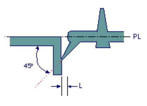
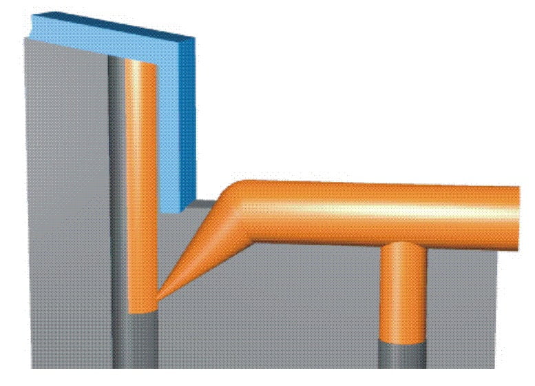
The submarine gate, tunnel gate, chisel gate, banana gate, cashew gate, and sub gate, can be placed in areas that are not visible; they are an option for molded parts that require perfect surface quality. It is used in two-panel molds, with an inclined cone-shaped tunnel between the end of the runner and the mold cavity, below the parting line. The gate is separated from the part when the part and runner are ejected. A typical submerged gate has a diameter of 0.25 to 2.0 mm, evolving from thick to thin until it becomes a spherical endpoint.
To avoid gate marks, a secondary gate can be set on the push rod, where the end of the second gate is connected to the inner wall of the product. The angle between the latent gate and the centerline of the branch runners is generally 30° to 55°, and a circular or oval cross-section is often used.
Pros
- Plasticizable.
- Self-cutting gate.
- Minor gate marks, eliminating subsequent processing.
- The gate position can be freely selected.
Cons
- High flow resistance.
- Not easy to process.
- More loss of pressure.
Hot runner gate
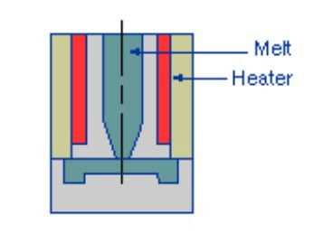
The hot-runner gate, hot-probe gate, and hot tip gate, usually transfer melt directly from the electrically heated vertical gate and heated runner into the mold cavity to produce a runner-less part. The solidification conditions near the gate of the part control the holding cycle. When the mold plate is opened, the plastic, which is quite hot, tears away from the mold cavity.
Valve gate
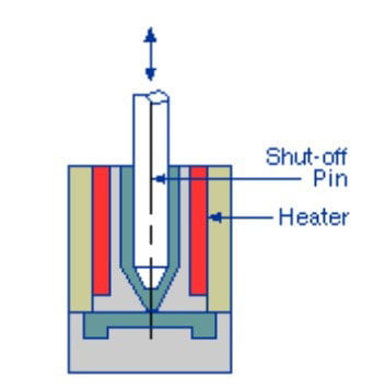
The valve gate, adds a pin bar inside the hot runner gate to close it before it solidifies. It can be used in larger gates without producing gate marks. Because the pin bar controls the pressure-holding cycle, the valve gate gives a better pressure-holding cycle and a more consistent part quality.
Gate design principles
The gate design should not be limited to the gate alone but should be considered in conjunction with the runners.
Properly designed gates allow uniform, rapid, single-directional transfer of melt to fill the mold cavities and allow proper solidification time to cool the molded part.
The gates should be shot at appropriate locations, such as non-functional and non-appearance areas.
Setting the gate at the thickest part of the molded part to allow the plastic to flow from the thick area to the thin area helps to get a good flow path and pressure-holding path.
Setting the gate located in the center of the molded part will allow the melt to flow to all extremes of the molded part with the same flow length.
Improper gate locations often cause problems and should be kept in mind.
The gate must be positioned, so the gas in the mold cavity escapes during injection molding. Otherwise, it will cause some defects like short shots, air pockets, burn marks, gate blush, or high-pressure buildup at the gate.
The gate location and size should also be designed to avoid the jet flow effect. Enlarging or improving the gate location to allow the melt to impact the mold wall can improve the jet flow effect.
Symmetrical gates should be used for symmetrical parts to maintain symmetry. If the flow path is not symmetrical, parts of the part will be filled, pressurized, and cooled first, resulting in uneven shrinkage and warpage.
If the location of the gate cannot avoid the creation of sutures or fusion lines, the gate should be relocated to a non-functional or non-appearance area.
The gate freeze time is the ultimate effective time for holding pressure in the mold cavity. A too-small gate allows the slowest solidification inside the part rather than at the gate. The gate may even solidify after the holding pressure has been removed, allowing the melt to flow backward from the part into the runner system. A well-designed gate must prevent melt backflow.
Smaller gates should be used at the beginning of the design; if necessary, larger gates can be used. The normal gate thickness is 50-80% of the thickness of the part at the gate. Occasionally the manually trimmed gates are the same as the thickness of the part, while the automatically trimmed gates are usually less than 80% of the part’s thickness to avoid distortion due to gate trimming. The end diameter of the pin gate and submarine gate is about 0.25~2.0 mm (0.01~0.08 inch). The shorter the gate length, the better to reduce the pressure drop in the gate area. The gate length is 1 to 1.5 mm (0.04 to 0.06 inch).
Plastics with added fibers require larger gates to prevent the breakage of the fibers through the gate. Smaller gates, such as submarine gates and pin gates, can damage the added fibers. Gates that produce uniform filling patterns, such as edge gates, can produce molded parts with uniform fiber mating.
Simulation analysis of injection molding is useful for comparing the effects of different gate designs.
